Spot Frequency mod for ICOM-735.
I noticed a few discussions on what was the best way to zero-beat a calling station when working CW. Someone touched on how in the days before transceivers, transmitters usually had a provision to generate a weak carrier signal that would beat or spot against the desired signal. Today's modern transceivers have the receive BFO offset the transmit frequency by a pre-determined amount. This produces the audible, pleasing tone to copy the CW transmission. The tone is typically about 600 to 800 hertz in frequency.
Well which one is it? If I adjust for 600Hz and my rig is set for 800 Hz, when I key my rig, I'll be off about 200 Hz.If the operator on the other end is using a fairly tight filter, I may fall out of his passband. I can recognize a tone fairly well, but I would not put money on being able to discern 600, 675, 700, 750, 800 Hz without some audible reference. There are a few devices out there which will give you an indication when you match a tone. That will work if your rig is aligned so that when you're in receive mode and the desired received signal produces an 800Hz tone. When you hit transmit your carrier should be right on top of the sending station.
Wouldn't it be great if you could switch to your transmit oscillator frequency just to tune in the station and then revert back to your ?regular? receive oscillator for the rest of the contact. You could "spot" their frequency as in the good old days.
I had to put this down in writing immediately after going through the process while it fresh in my mind. I also have a mod to correct the downward carrier shift when in AM mode documented elsewhere. But that's another story.Here are the design parameters:
No nasty holes in the rig.
No mods that could not be undone without major surgery.
The mod can be removed in about five minutes. The type of switch you use will determine how big a hole you leave in the bottom of the rig.
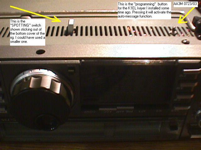
I have made three mods to my 735. One was the keyer installation. I couldn't see spending $50 to $150 for the factory keyer. I'm sorry. I installed the K1EL keyer for only $8. No cut wires and can be removed without excessive pain.Mod number two was to correct the downward carrier shift when in AM mode. On my rig at nominal modulation levels, the ALC circuit would pinch the carrier and slowly recover to a static zero modulation level. You could watch the AM carrier and modulate. After the modulation, the carrier would recover slowly, a second or two, to the zero modulation carrier level. Annoyed me to no end. A single 2N2222 and two resistors corrected the problem. You can see the mod HERE.
Mod number three. This is a honey of a rig. Plenty of discrete components and documentation. The key to this mod is to switch to the transmit CW oscillator when you hold in a button. This will put your transmit frequency into the receive mixer momentarily. You turn on the transmit oscillator by pressing the button, tune the station for a zero-beat, and take you finger off the button. When you key your rig, you will be very close to the received station's frequency.
If you are squeamish about cutting a lead on a transistor in your rig, run away now. The correct thing to do would be to unplug all the neatly harnessed connectors and remove the board. That didn't happen! Remove the transistor, bend the base lead up, and replace the transistor. This mod took about an hour to perform. Most of the time was spent locating the components. I attempted to assist you in locating the components by providing some pictures with captions.
I guess I should also give the mandatory disclaimer that I will not be held responsible for any damage that may occur to your rig in the process of performing this mod.
A generous friend of mine (Dennis, WB8WTU) shared his maintenance manual with me to work on this mod. Without his generosity, this mod would not have been possible.
Tools needed:
Fine tip soldering iron.
Precision wire cutter
Magnifying glass.
I have a fairly long fine tipped iron. Be careful not to melt nearby wiring harnesses when soldering on the board.
There is a nifty offset cutter that would reach in and make the chore of cutting the transistor lead a snap. I don't own one. I do have a cutter with a fairly fine point. You cannot use a regular cutter. It won't let you get close enough to the board to leave enough lead on the transistor to bend up.
Good vision has been a gift I was fortunate enough to have for over forty years.
In my twilight years, it has become necessary to increase the number of photons on an object to improve the visibility. The schematic in the manual is about one step up from microfilm. Fortunately to make this mod you do not need to have the schematic, unless of course you would like to see what the mod does to the circuit. But you'll still need a magnifying glass if you wish to inspect your soldering connections.
Parts List:
One 82 ohm Ľ watt resistor
One 3.9k ohm Ľ watt resistor
One SPST momentary switch
With that said, let's get on with the mod.
Let me also mention now that my rig does NOT have the optional CW filter. This may be an issue with some rigs, but I have no way of verifying this. Hopefully someone with a filter will try this and get back to me.
The Q37/Q38 oscillator using the crystal X4 switches between two modes.
A receive and a transmit mode. Pin diodes switch between one set of capacitors and another to set the transmit carrier and receive BFO frequencies.
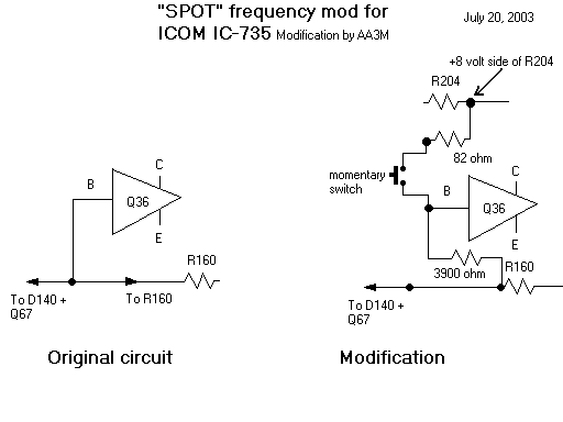
The base of Q36 is the control point of the switching. If the transistor is turned on, one set of parameters is in effect. Turn it off, another set. The spot mod consists of manually intervening in this switching process.
Another thing I should mention at this point. The print in the manual is small. I could get around it somewhat by blowing up the schematic in the copying machine. The board doesn't blow-up real well. I have to admit, I used a magnifying glass to locate and verify the components. Discrete components, yes, but fairly small..
So here we go..
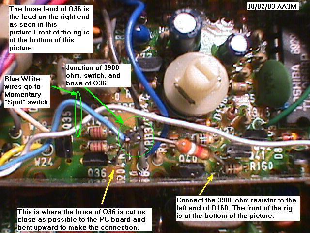
Locate Q36. Cut the BASE lead. It's on one end of the transistor. You want to cut it as close to the circuit board as possible.
When I cut my lead, I had a little left sticking up out of the circuit board, just bend it down out of the way for now.
We're going to insert a 3900 ohm resistor in series with this base circuit.
I tack soldered a 3900 ohm resistor to the base lead of the transistor and tacked the other end of the resistor to one end of R160. It's the end that if you were to trace it back, it connects to the base of Q36.
That effectively re-connects the base back into the original circuit, but with an additional 3900 ohms in series.
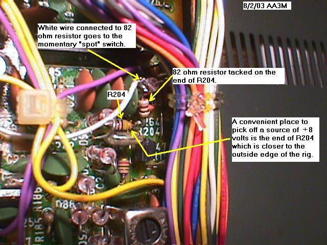
Now we add momentary SPST switch to connect the base of Q36 to the 8 volts source via an 82 ohm resistor. A convenient source of 8 volts was one side of R204. It was the outboard side, away from the middle of the board end of the resistor. You can confirm this with a multi-meter, one end of R204 is less than a volt, and the other is almost 8 volts in receive. (and transmit)
Here's the hard part. Make a hole in the bottom of the rig.
I found that it wasn't so bad making holes in the ventilation louvers in the bottom of the rig. If I was a purist, I would buy a new bottom, remove all the mods, and replace it when I sell the rig someday. But the holes are so insignificant and the mods are so useful, I find no reason to remove them.
The hole in the bottom is to accommodate the pushbutton switch for the spot function.
I salvaged an ICOM switch from an old auto-tuner box, but any SPST momentary switch will do.
The switch is located so I can use one hand to press the button and "spot-tune" using the tuning knob.
That's it for the mod!
In the rare event that you would wish to revert to the original configuration, you remove all the added components. And then re-connect the Q36 base lead back to its original board connection.
Another approach would be to remove the 82 ohm and switch, leaving the 3900 ohm resistor in the circuit. It has a negligible effect on the original circuit operation.
If one picture is worth a thousand words, please checkout the four roadmap pictures for navigating inside the rig. Click on the links.
Picture One - Bottom cover view. Front of rig towards you.
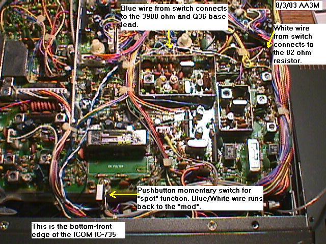
Picture Two Cover removed, general location of mod inside the rig.
Picture Three Close-up of Q36 + R160
Picture Four - +8 volt source / R204 close-up.
Picture Five Bottom of rig, cover removed, showing switch installation and wire route.
Good luck and feel free to contact me with any questions you might have concerning this mod. You may e-mail me via www.eqsl.net. Sign in and do a call search on AA3M.
73
John AA3M