
This information is for owners of the Kenwood TS-850S transceiver and the Yaesu FL-7000 amplifier.
I recently purchased the FL-7000 amp and quickly realized what a shame it was not to take advantage of all the features the Yaesu
folks designed into the unit. The amplifier will not only change bands, it will remember the settings of it's built-in antenna tuner
for each band. With the optional FAS-1-4R remote switch, it will also switch to one of four antennas for each band setting.
I was primarily interested in finding an inexpensive ( cheap) interface to have the band data information of the Kenwood drive the Yaesu
amplifier. Slight problem. The Kenwood TS-850 was designed to "talk" externally via it's RS-232 serial connection.
The Yaesu "talks" Yaseu band data format. Basically a binary representation of a value 1 through 9.
The amplifier is fairly sophisticated with a microprocessor controlling the amplifier's main functions and another dedicated
to the autotuning function. Serial communication with the outside world was not seen as a necessity at the time it was designed.
The unit will work quite nicely with most other Yaesu transceiver models with their band data connections conveniently brought out
to an accessory connector. There are third party interface units which will read the Kenwood serial data port, and convert the data
to the required Yaesu binary band data format. Needless to say they cost a few dollars.
I did more research and discovered where another amateur Winfried, DK9IP, clearly illustrates how he connects to the 850's filter unit
to bring out the nine outputs representing the band data information.
(I hope he doesn't mind me providing this link to his page illustrating that process.)
Here's the link to his site: http://www.dk9ip.de/projects/banddecoder/banddecoder.html
What I did was to copy that aspect of the process and build an interface which converts the 9 states representing band data and convert
that to the binary format required by the Yaesu amplifier.
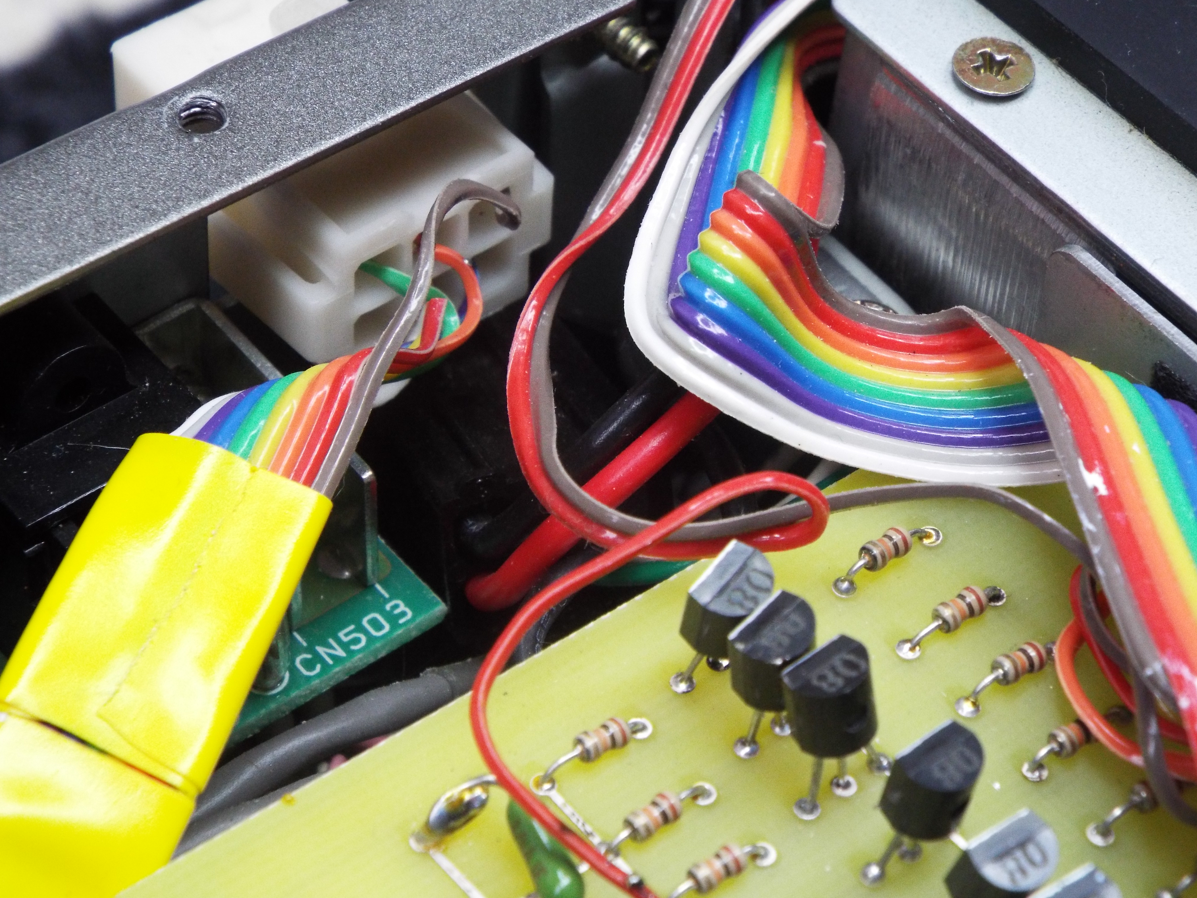
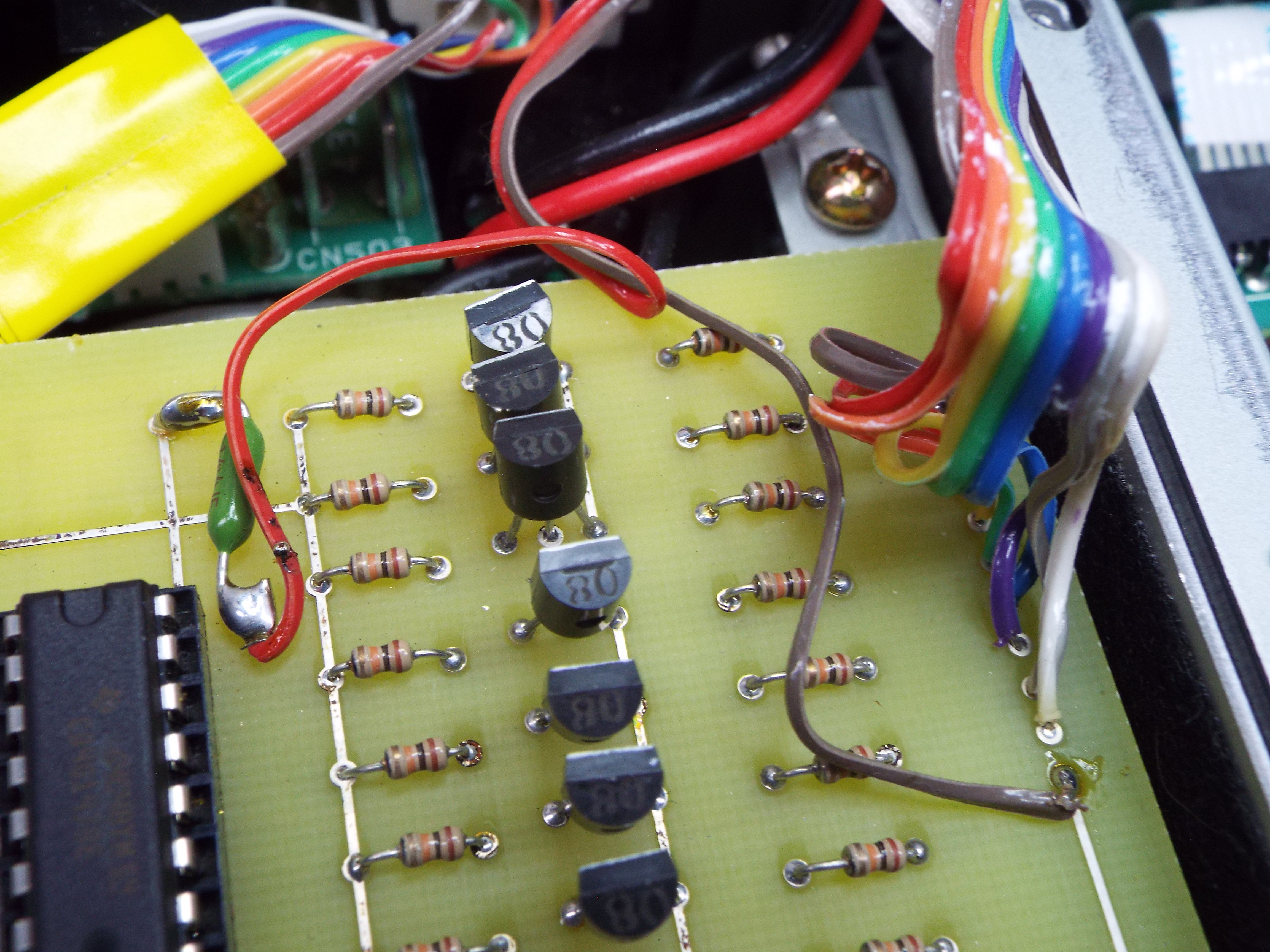
Here's a photo of the bare board.
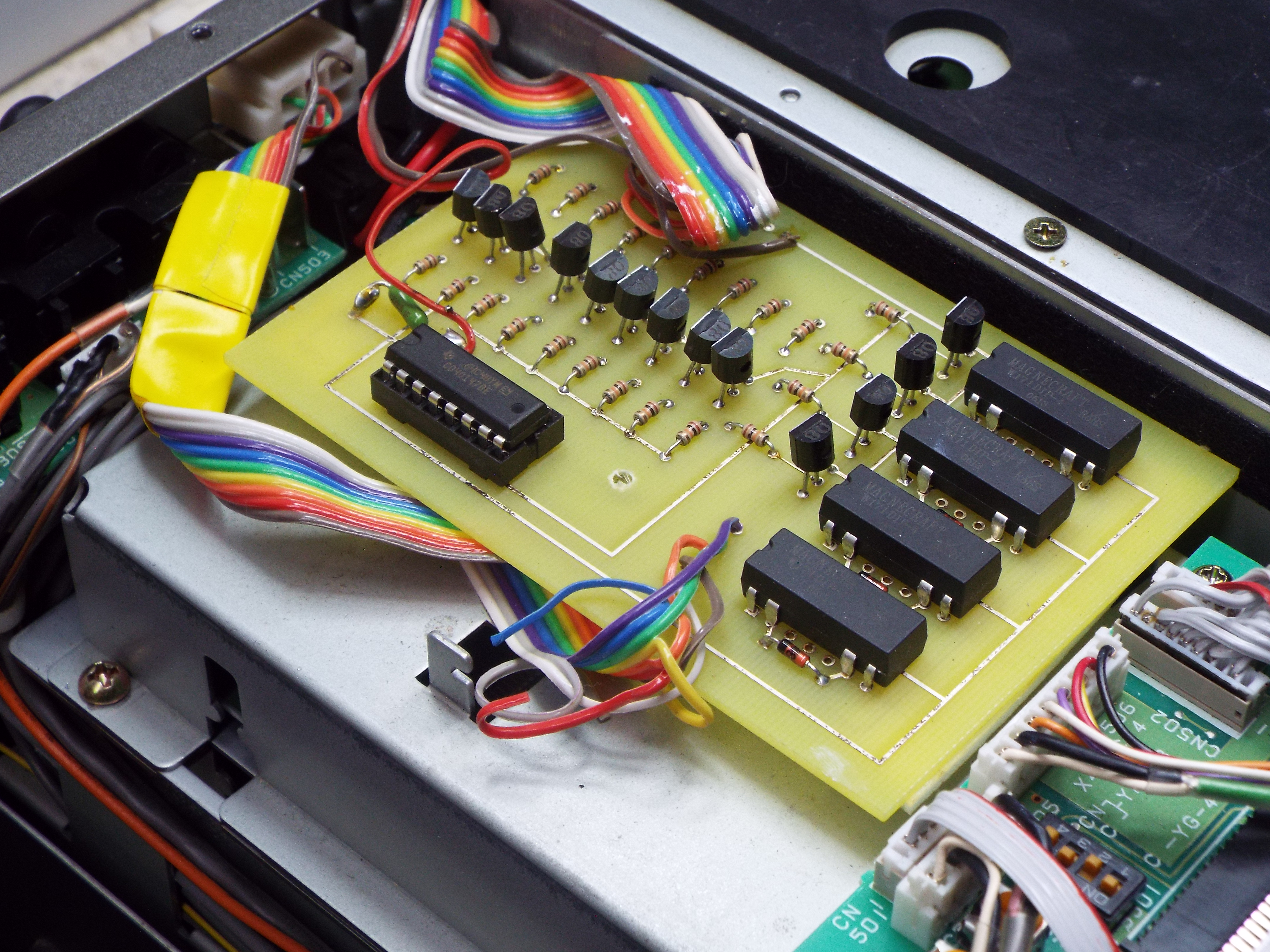
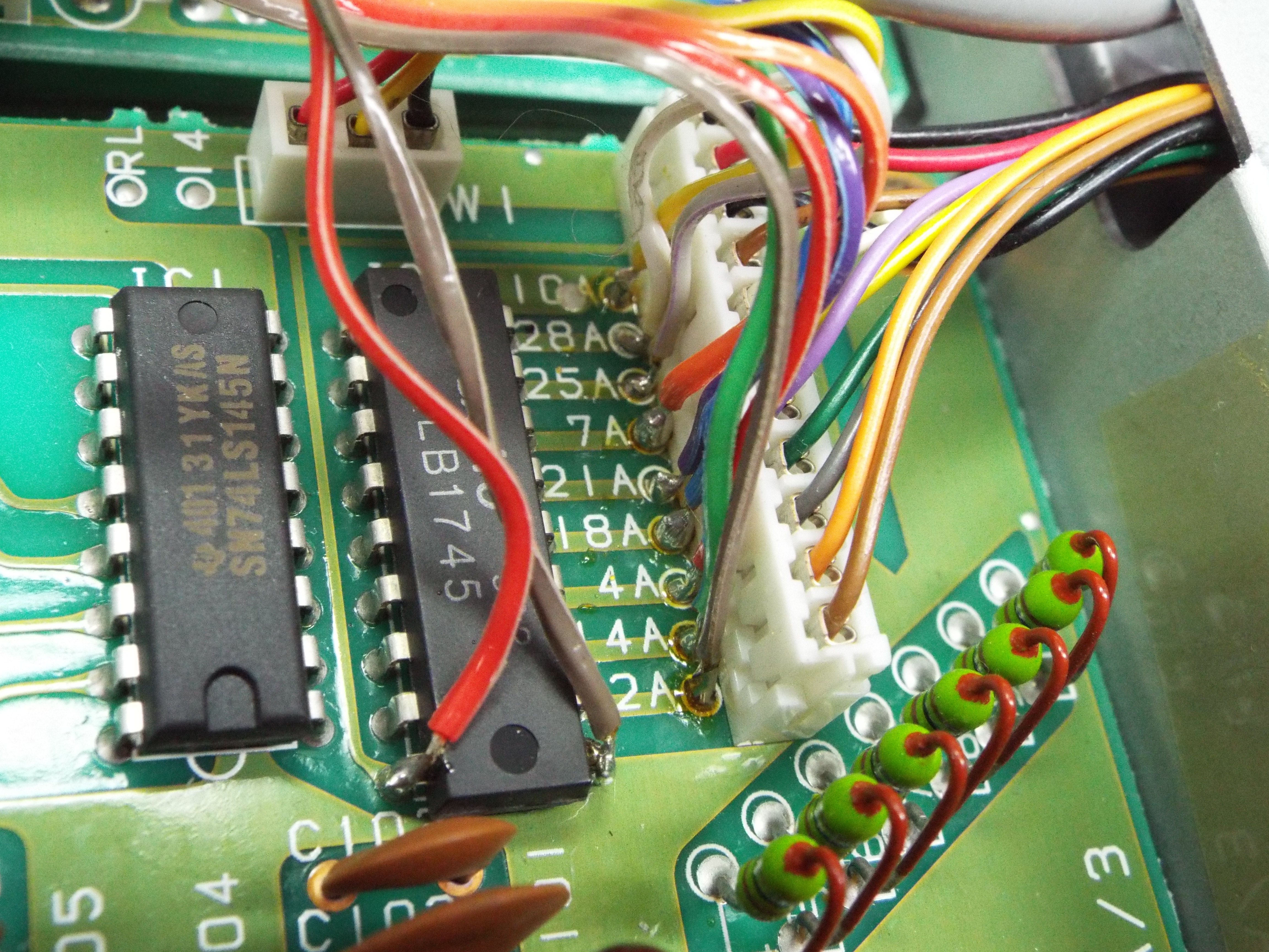
A photo of the completed board.

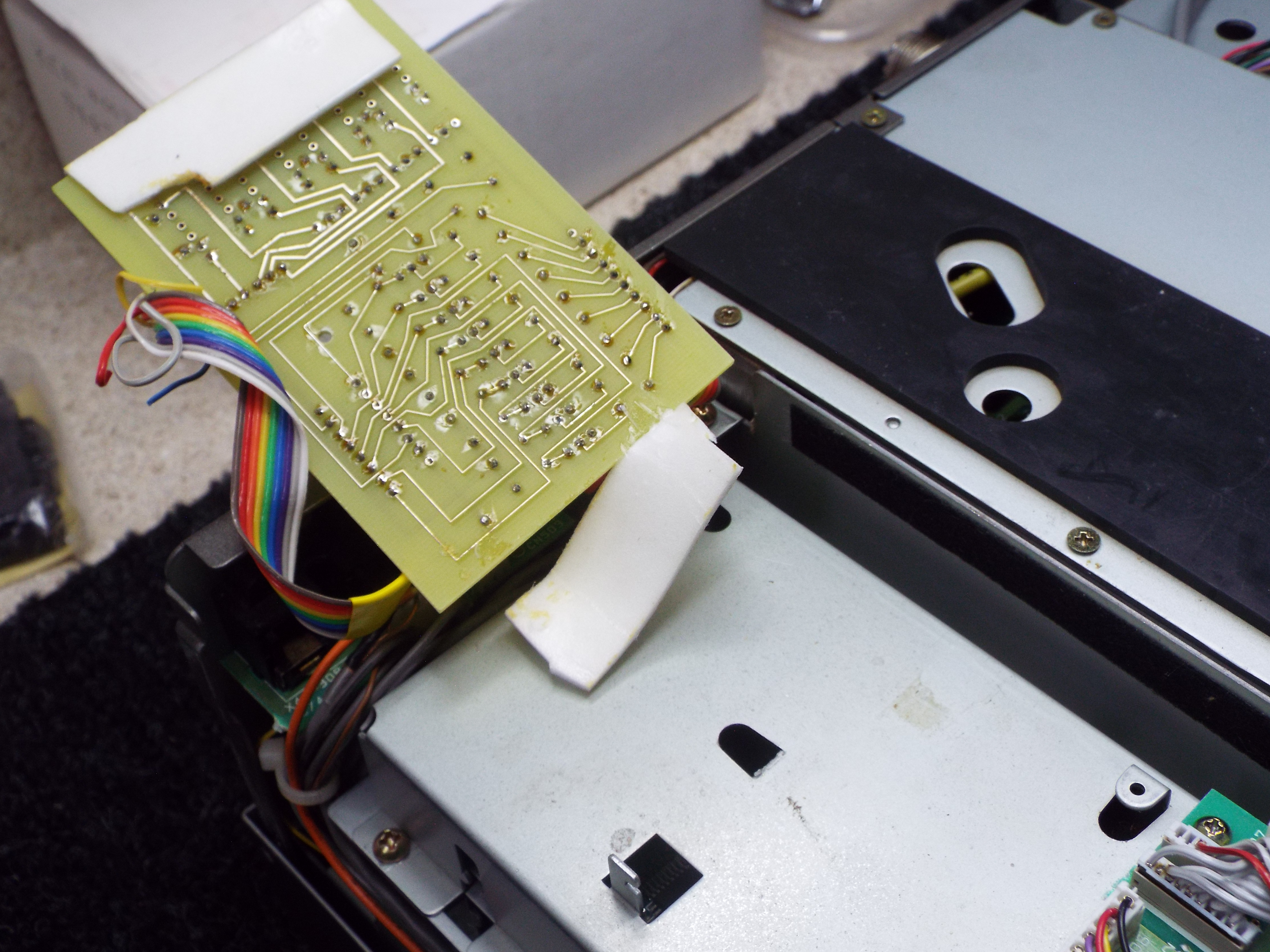
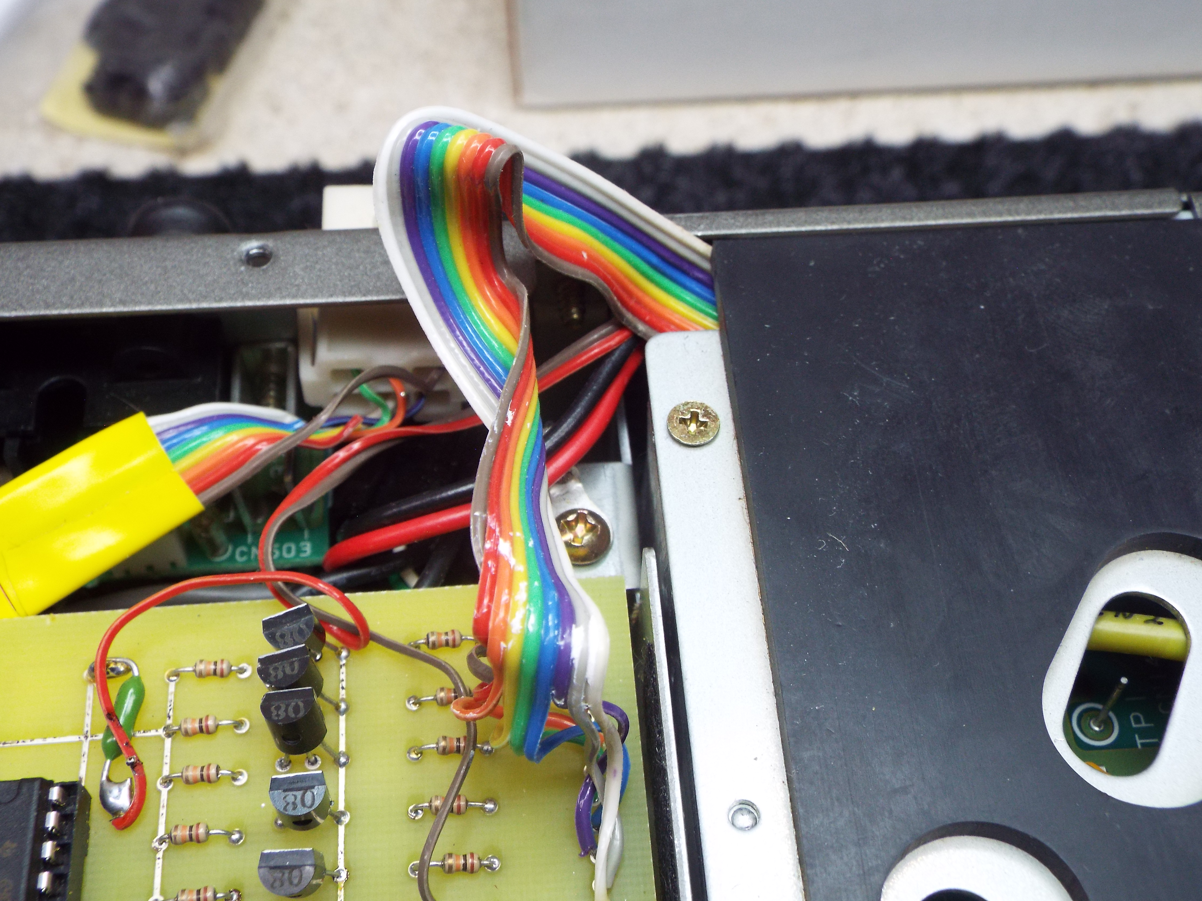
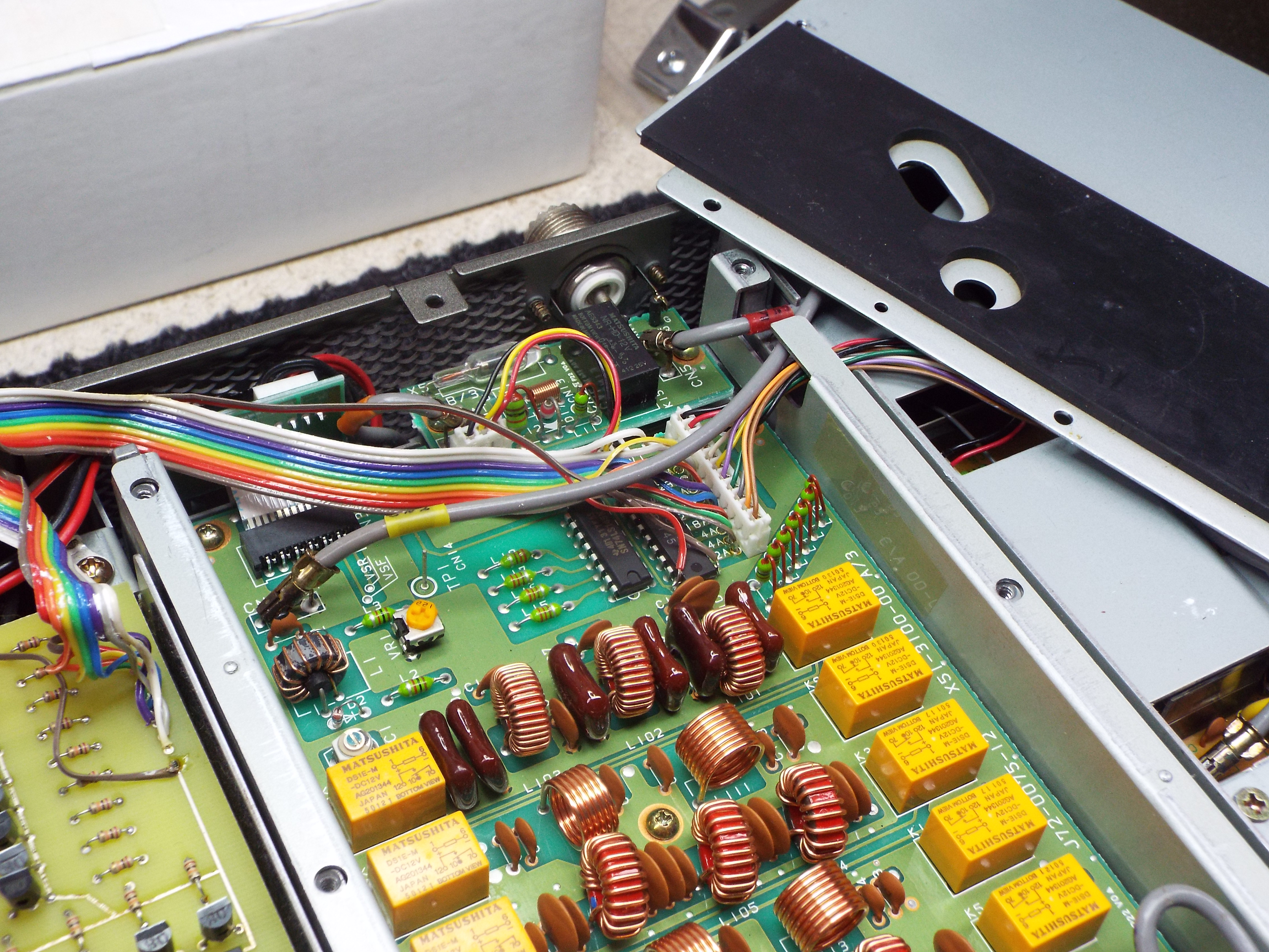
The board installed in the 850.

The six pin connector on rear panel.

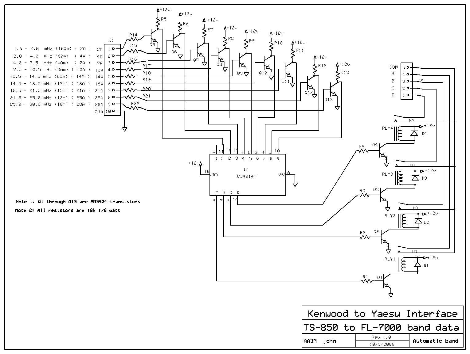
The schematic in .jpg form here.
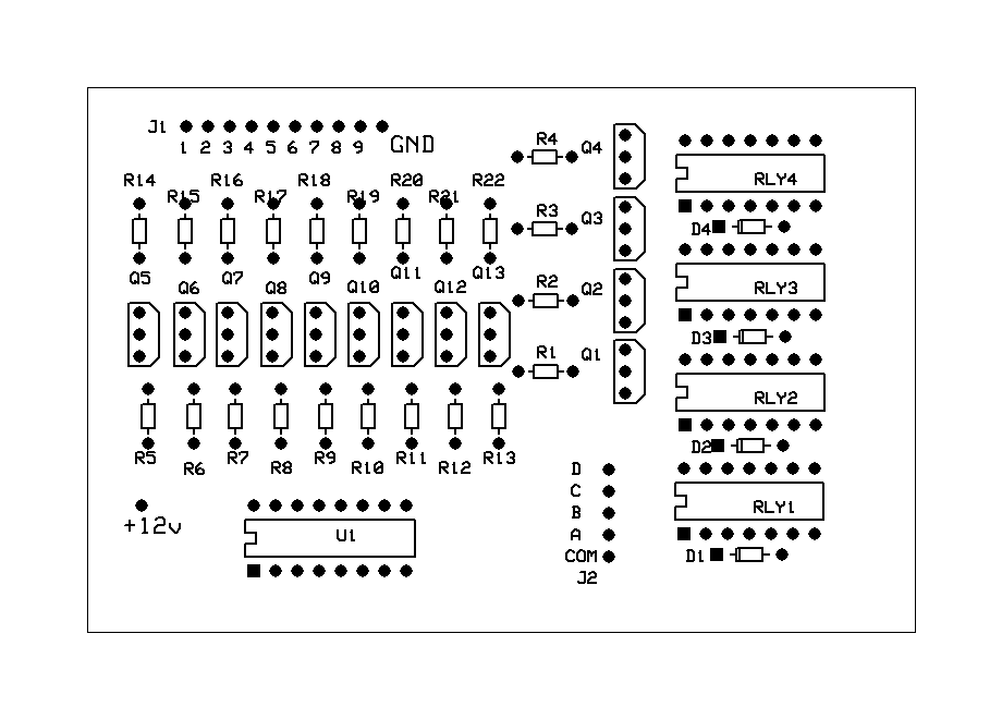
The component layout on the board. here.
And finally the parts list in Excel format. here.
I designed the board to be as simple as possible to assemble. All the components are of the same value.
There is a total of 13 transistors, 22 resistors, 4 diodes, 4 relays and the CD40147 IC. That's it!
If you have to order the parts, you're going to have to wrestle with the fact that 22 resistors will cost you $1.76 while the same ones in quantity
of 200 will cost you about $2.80. Bulk pricing....
Confession time. I did perform one "bad" thing during the installation. If you have the optional digital voice board installed
you're out of luck for a clean internal installation. I mounted my board in the top of the unit directly under the access cover.
And here's the "bad" thing I did. I broke off the center mounting bracket which would normally be used to mount the optional board.
I'll provide photos as soon as I revisit the scene of the crime. With this bracket out of the way it is a no-brainer getting the
board to fit. Double sided tape and you're on your way. You could get away without breaking off the bracket. I don't know what I was thinking
at the time. It's not necessary to remove it and the bracket died a needless death.
You may notice a hole near the middle of the board. That was where I attempted to take advantage of that bracket which I wound up removing.
If I had more patience I could have utilized the bracket. Nothing I hate more than drilling or permantently "modifying"
a piece of equipment.
One diversion from Winfried's installation I want to attempt is to find a replacement molex plug for the antenna tuner one you set aside
to make room for the DB9 on the rear panel.
I found a six pin connector which almost fits. Look at the photo closely and you'll notice a cable tie wrapped around the connector shell. The tie forces the "ears" of the connector outward to fasten it securely in the panel opening.
You only need five pins for the interface to the Yaesu amplifier. Using the six pin connector, you will even have one to spare.
You may have noticed I also have a pico-fuse as a last -minute thought. I'll add it to the board layout on version #2
As with most of these home-brew projects I have a few circuit boards left over. If anyone is interested I can put together a kit which would include board, parts and shipping for $55 US.
If you're interested in more info before it's posted, you can reach me at rotor#aa3m.com ( substitute an @ for the # sign in the address.)
73 John AA3M
More photos added 26MAY2015