There's an easy way out for you if you are uncomfortable about installing the lightbar.
Disconnect the front panel and send it to me.
I'll install the lightbar ( and optional dimmer if ordered) and send it back to you.
PLEASE - DO NOT SEND ANYTHING TO ME WITHOUT FIRST CONTACTING ME. THANK YOU
Here's a shot of the rear of the front panel showing the cables to be disconnected and the 6 step checklist of disconnects.
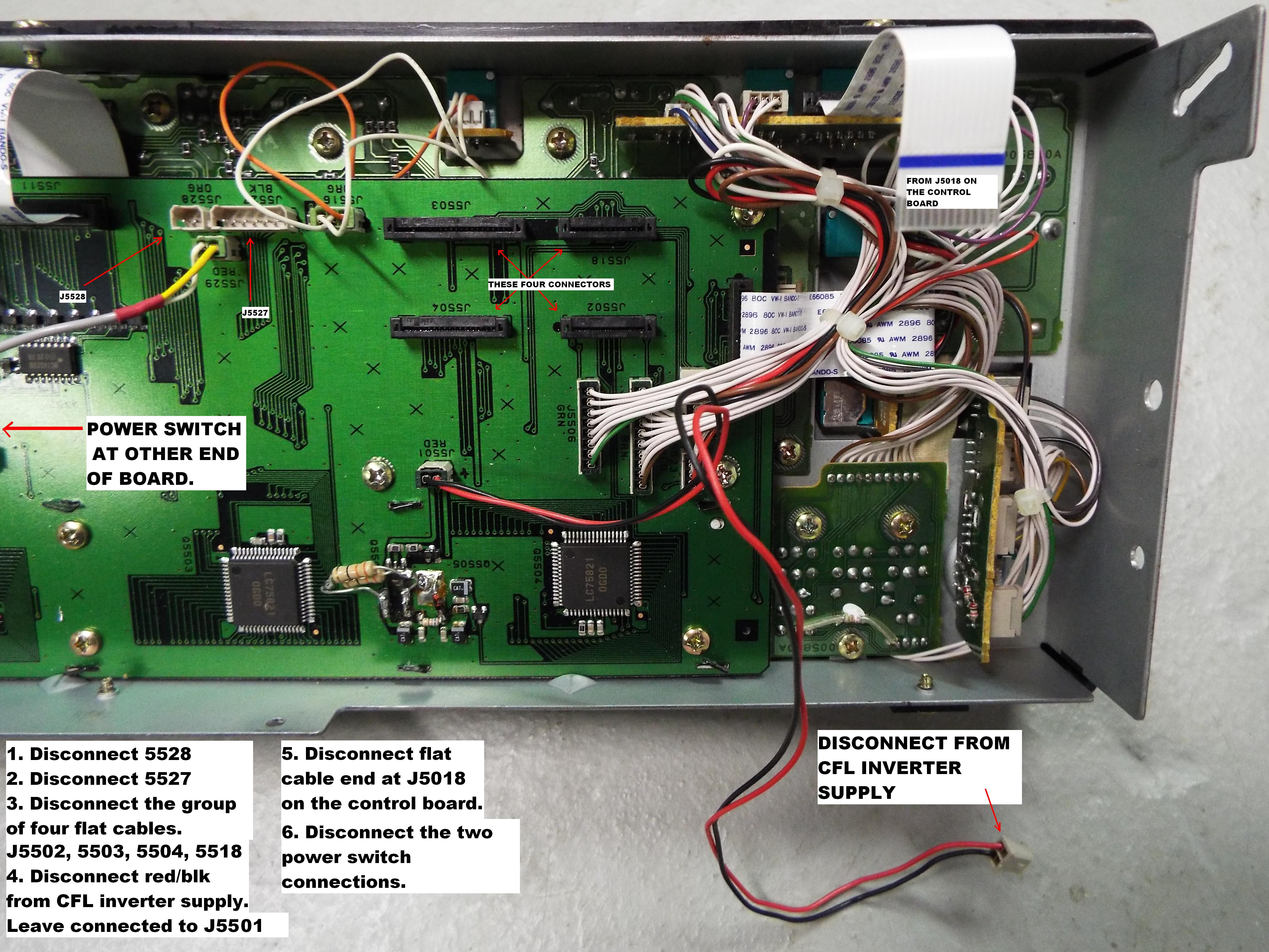
Step 1 and Step 2:
J5528 and J5527 are pretty straight forward. Grasp the wires at the connector with your fingers and pull firmly.
Step 3:The flat ribbon cables (J5502,J5503,J5504,J5518) take some care as not to break the locking clips. On either end of the connector you will notice a slight lip. Use your fingernail to lift the lip away from the board.
It does not move real far. Maybe a sixteenth of an inch (abt 2mm) and it will stop. DO NOT FORCE IT ANY MORE THAN THAT, IT WILL BREAK!!! Once both sides are lifted, the cable will lift out without any problem.
NOTE: It is possible to remove the locking clamp on the connector without "breaking" the connector part on the board. The problem is that once that clamp has been slipped off, it loses it factory-fresh stop protrusions on the sides of the connector. When the clamp is replaced, it will lock the wires securely in place. But in the future if you remove the flat cable, there is less plastic on the stops to keep the clamp married to the connector on the board and it may fall off and get lost. Another consideration is the orientation of the clamp. It will only go on securely in the direction it came off. Compare the small "holes" on either side of the clamp end and match it with J5511. (J5511 does not need to come off for shipping so it should be correct.) All 4 should match J5511's clamp orientation.
If you are 100% clear on this, please do not hesitiate to ask me for my phone number and I will walk you through this step.
******************************************************************************************************
While we're on the subject. Reconnecting the cables is done in reverse order. Before inserting the flat cable be certain that the locking clip is in the raised position. Insert the cable until it bottoms out in the connector and while keeping it in position, press the locking clip down until it stops. Preferably both ends are pressed down at the same time. A visual inspection and a slight tug on the cable will confirm that it is correctly installed. If not, lift the locking clip and try again.
************************************************************************************************************
Step 4:
The CFL inverter is mounted on the front chassis panel ( sandwiched between the front panel and main chassis). You have to remove the inverter shield cover and disconnect the red/black wire that powers the inverter. The other end of that lead is connected to J5501 on the display board end. Leave it connected to J5501 on the display board for shipping.
Step 5:
There is a flat cable running from the SPEED/PITCH sub-board and connects to the control board connector J5018. Disconnect that cable at the control board end. MUCH MUCH easier than trying to manipulate the connector on the sub-board end. (fat finger disease)
****** Leave the flat cable attached to the SPEED/PITCH sub-board for shipping. ******
Step 6:
Now remove the leads that connect the power switch to the main chassis. There are two white connectors just inside the main panel. Depress the clip and the connector will pull out of the socket.
A few final reminders. You should have only disconnected the four flat cable indicated in the photo and leave the SPEED/PITCH sub-board cable connected to the front panel.
Make sure the red/black wire pair from J5501 is still attached to J5501.