In addition to adding a dimming feature to the display, any RFI from the CFL lamp supply has been eliminated. Prior to the mod I was able to hear birdies about 50kHz apart all the way up and into the lower end of the AM broadcast band.
*****UPDATE It's now confirmed that the lightbar will work in the FT-1000MP Mark V field.
The only difference in the installation, as compared to the Mark V, is that there is no need for the two voltage dropping diodes. The Field seems to have a 10 volt regulator supplying power for the CFL circuitry. In any case be certain that you are not exceeding about 10.5V to the lightbar at maximum brightness.
****UPDATE: Version 3.0 is ready. Assembled. ****UPDATE: Plug-in version of dimmer circuit will be released near end of 2013. No modification of the display board is necessary and only two simple soldering connections are required for installation.**********UPDATE UPDATE********* Do not drill the rear of the rig!!! Chuck WD8BXS mounted the pot on the top of the rig and I must admit it's the logical place for it.
I liked it so much I moved my own from the rear panel to that top cover location. Here's a photo.
**** UPDATE: I gave in and decided to mount a 100k pot on the rear panel. There is plenty of space between the DVS-2 and CAT connector and a nice route along the underside of the rig. ***
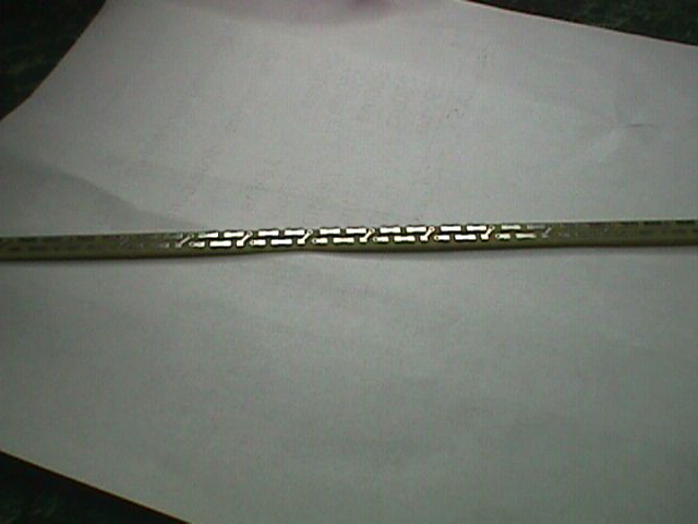
I resorted to using a pair of 1N4007 diodes to provide a loss-less voltage drop to lower the "high" display setting. It (light bar) ran warmer than I was comfortable with and ran for days without failure. The diodes brought the current down from 280ma. to 210ma. (the CFL draws 250 to 290 ma.) The drop in illumination is negligible and lowered the dissipation to a comfortable level. **** UPDATE: Version 3.0 has more LEDs and draws about 260 ma. on HIGH I'll be the first to admit to you that this is NOT an easy mod. There is the matter of soldering 1206 package SMD components. (You should have seen me working with version 1.0 that used 0603 SMD packages. I could barely see the cathode mark using a magnifying glass.) The end mounts to hold the light bar in place require "creativity". If I revisit the light bar, I could try using silicon glue to hold it in place. I didn't have the patience to wait for the glue to dry and wound up cutting small grommets as end mounts. Maybe rubber "O" rings? If you have to replace your CFL, then this may be worth your while. To replace the CFL you have to take the display apart. Since you're that far along, this mod may be a consideration. If you're not comfortable with taking the LCD display apart, run away! The HIGH /LOW (variable) mod made the CFL replacement worthwhile. (Besides correcting the annoying delay start that started this whole mess!) Good Luck and be content with the knowlege that there is a "cure" for that display problem. As soon as I have an opportunity to publish the details (schematic) of the dimmer circuit and photos of the completed mod I will post them. A kit should be available around the beginning of August 2009. ****UPDATE: Can supply limited number of version 3.0 boards, and / or kits at this time. There are 90 LEDs and 30 resistors. Building time is about three hours. You'll need a magnifying glass and a fine soldering iron to build the kit. My email address is good on QRZ.Com 73 John AA3M Here's a photo of the version 2.0 solid-state light bar replacement for the FT-1000MP Mark V display.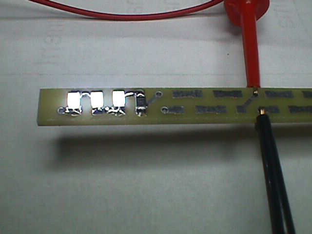 Nearly full length shot of version 2.0 bare light bar.
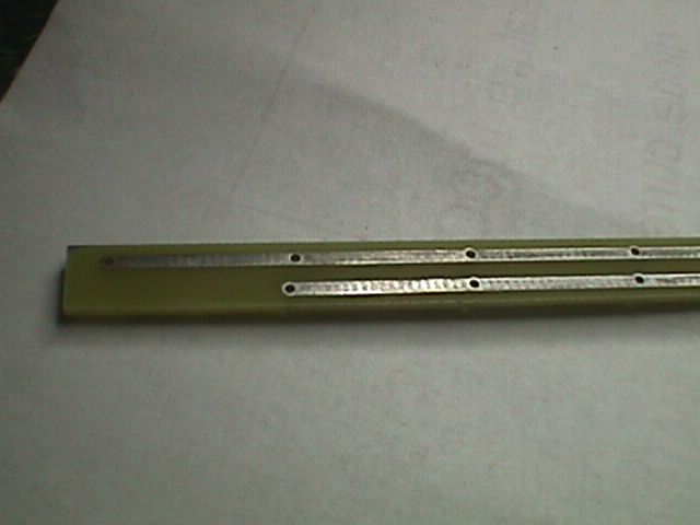
 Rear view of board showing version 2.0 power bus.
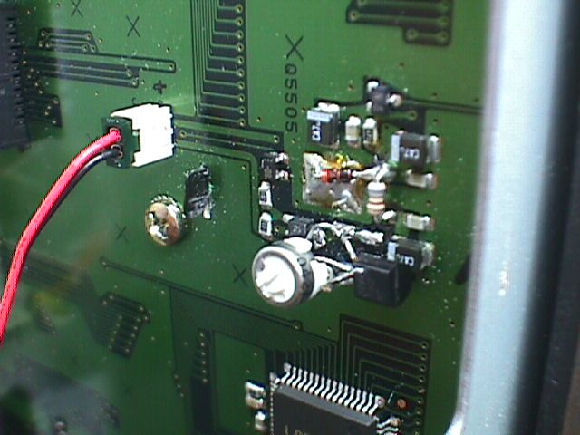
 View of light bar dimmer components location.
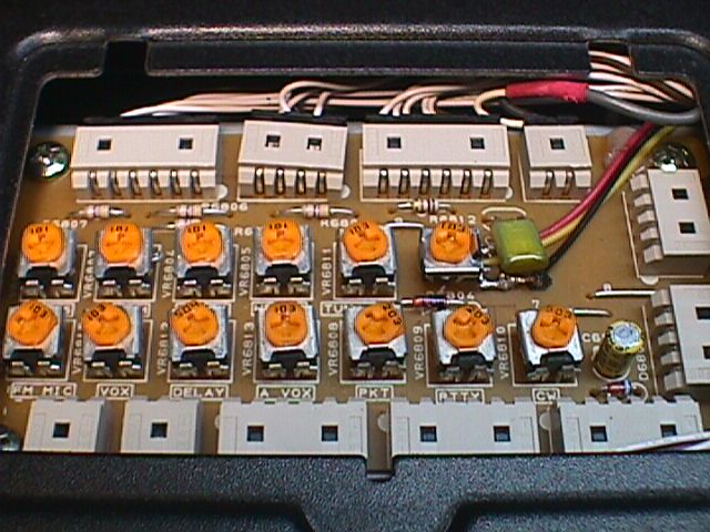
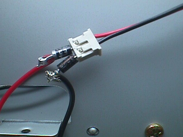 CFL supply just a tad too high, two 1N4007s provide just enough voltage drop to keep LED current within a conservative operating range.
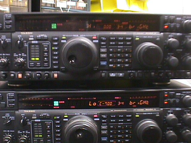 Pardon the poor quality of the photo. Top "un-modified unit is using the "Hi" setting, lower unit is using "Low".
An interesting observation is that at about 45 degrees off of center (left / right), the two displays appear have about the same luminence. (Not visible in this straight-on-view photo)
Pardon the poor quality of the photo. Top "un-modified unit is using the "Hi" setting, lower unit is using "Low".
An interesting observation is that at about 45 degrees off of center (left / right), the two displays appear have about the same luminence. (Not visible in this straight-on-view photo)
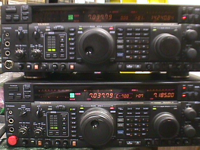 Ok, Ok Here's another view. Upper(un-modified) and lower units both set on "High" display setting.