
The bare board accommodates 90 SMD LEDs on the front and 30 SMD resistors on the back.
Power is fed at the end of the board to the power bus which feeds 30 groups of three LEDs.
When soldering the LEDs you must follow the convention of alternating the three diodes in each group
That is, cathode up, cathode down, cathode up. You may also use cathode down, cathode up, cathode down.
up, down, up *** up, down, up *** up, down, up *** up, down, up *** up, down, up *** up, down, up *** up, down, up etc.
or.... down, up, down *** down, up, down *** down, up, down *** down, up, down *** down, up, down *** down, up, down etc.
The only difference will be the polarity of the power bus.
Repeat that pattern of three across the entire board. up, down, up. next group of three: up, down, up
The dot (cathode marker) is rather small so you will need some sort of magnifier.
It would also be useful if you bought a few spares incase one or two get messed up during the soldering process.
The LEDs are available from Digikey LED p/n 160-1737-1-ND description: LTW-150TK
and the resistors are available from Mouser p/n 632-CR1206FX-1300ELF description: 130 ohm 1% 1/4 watt resistors.
They come in strip carriers and you should only peel out a few at a time as you work on them.
While you're ordering from Mouser, you might as well get the pot for the dimmer mod.
It's Mouser part number 858-P0915NQC20BR5K description: 9mm 5k ohm potentiometer.
My magnifier has a lamp in the housing.
The important thing to remember is to alternate the LEDs and maintain that pattern for all the groups.
If writing it down in front of you helps, then do it.
When the LEDs are mounted, don't forget the resistors! Been there, done that.
Now that the eye straining, back breaking work is done, it's time to check your work.
If you have a small 10 volt power supply at about 250 ma. , Super.
If not, A 12 volt one will work, but try not to keep it on too long. Five to ten seconds should be OK.
The thing to keep an eye on are the dropping resistors on the back of the board.
Too much voltage will increase the LED current and cause the resistors to overheat. They are only rated at 1/4 watt.
At the 10 volt full brightness, the LEDs are operating at about half their maximum rating.
The 10 volt level is more than adequate. There are two reasons for keeping it at 10 volts.
The lightbar operates in a closed environment (the LCD housing) heat build-up.
Also more photons will not necessarily result in a better looking display.
With more light, the LCD panel will appear to be washed out. That's the nature of the beast.
Now that you've got the lightbar assembled and tested, it's time to install it.
For those of you who like step-by-step, let's try this:
BEFORE YOU DISCONNECT YOUR RIG AND PUT IT ON THE BENCH.....PERFORM STEP 1.
1. For those with an operating display (not dead), select HI in menu 3-4. If the display is not working, it is not the end of the world. You can set the menu once the lightbar is installed. (Maximum brightness is adjusted while using the HI setting.)
2. Remove all the covers on the rig. You could cheat and leave the two small side covers in place if you loosen their screws just a bit.
3. If you are shipping me the front panel please follow these instructions. -> Panel shipping instructions.
4. For those of you performing the installation yourself, tilt the front panel down ( see Access to the display board info on this page)
5. While adding these step-by-step instructions I realized that the display board removal instructions do not contain any info on how to remove the board. That lack of detail will be addressed in the future. The only wisdoms I can shed on that process is be very careful when releasing the locks on the flat ribbon cables. They only move perhaps a 1/16 of an inch to release the cable. THEY DO NOT COME OFF. If they do, it broke.. Also, you should mark all cables with the connector number as you remove them. Some are not intuitive where they belong.
I suggest that you have a few small containers to put the screws in while you disassemble the rig.
It makes it a whole lot easier to only have to remember each group rather than guess which one out of the whole bunch.
The screws that actually hold the housing in place appear to have a slightly coarser thread than the other same length short screws.
You may want to keep those separate from the others.
Before proceeding, you should verify that you have the lightbar wired and tested.
Let's keep it simple and use RED for positive, and BLACK for negative.
All assembled lightbars come with the power leads attached.
Connect the lightbar to a source of 10 volts and make sure it's illuminated and the polarity is correct with respect to the power supply.
Red lead to positive terminal and Black lead to the negative terminal of the power source.

You may want to put down something soft to prevent marring of the finish while you remove the covers.
Remove the top panel by removing the four side screws(two on each side)and the two on top. (Do not attempt to remove the four screws surrounding the speaker.)
Lift the panel from the rear (next to the heat sink) and pull the sides out slightly.
Carefully unplug the speaker wires and place the panel aside in a safe place.
Remove the 4 side screws holding the rear panels.(two on each side).
You will also want to loosen (BUT NOT REMOVE) the side panel top screws.
There are two on left side as you view the rig, and two in the space between the heatsink and side panel.
DO NOT REMOVE THEM.
Here's the view with the top front cover removed.

Flip the rig upside-down and remove the bottom and side screws if you didn't already remove them.
Remove the bottom by lifting the bottom panel up starting from the rear and place aside a safe place.
Now flip the rig right-side up ( be careful because the rear side panels are only being held by the two small ones on top).
Remove this top screw holding the front panel on both sides.

Now loosen the bottom screw on both sides, but DO NOT REMOVE THEM.

Once you've got the side screws ready, remove the top two screws. CAUTION!!!!!!!!!!
Front panel will want to drop once you remove the second screw.

The goal here is to tilt the front panel down to gain access to the display board.
Fortunately the display panel sits on top of the control panel.
In the photo below, you may want to take note of these two screws that hold the LCD housing to the circuit board. To their left is a hole in the board where one of the
display board mounting screws has been removed.The LCD housing screws appear to be a coarser thread than the other small screws. I suppose to bite into the plastic as opposed to through the metal.
You'll need to remove the front panel AGC and ATT control knobs. It will help to get a Q-TIP ( small stick with two cotton ends) and cut it in half.
There are several types of ribbon cable connectors. The ones used in the Mark V are the kind with a locking ring that secures the flat cable.
It's not the type where friction alone holds the cable in place. To remove the cable ( and re-inserting it ) You'll have to lift the locking ring at the top of the connector.
Using your fingernail, or a small screwdriver, gently/firmly lift the top edge of the connector on both edges of cable.
It will travel only about 1/16th of an inch, (about 1 mm.)and stop. The ribbon cable should pull right out.
You should not have to force the cable out, it will be fairly free at that point.
Re-inserting the cable is the process in reverse. Assure that the locking ring is raised the small amount and insert the ribbon cable.
You should feel the cable bottom out as you plug it into the connector. Use your fingernail or a small screwdriver to press the locking ring down into position.
Gently pulling on the cable will confirm that it's locked into the connector.
Don't forget to mark each cable as you remove it so you'll know where it goes when you re-assemble the panel.
I wrote the last two digits of the socket designation on the connector with a fine point marker.
Unscrew the CLF power supply from the front of the chassis. Three screws on the cover and two holding the board to the chassis.
Save the red/black power lead that connects the CFL supply to the circuit board.(J5501)
Once the screws are removed holding the display board to the control panel, (don't forget the recessed one on the left as viewed from the front.)
you should be able to lift the panel out. Remember that Q-TIP?
Remove the panel and place it aside. Now put the Q-TIP cotton end into the pushbutton where the switch shaft normally goes.
It will leave you a convenient handle to get the button back into position and more importantly,
keep the button from escaping down in between the control board and the front bezel.
If the button escapes, you've got more work than you bargained for.
"So John, How do I remove the Q-TIP once I stick it in the button?"
I used a small screwdriver to pin the button down in it's proper position while I remove the Q-TIP.

Here's the front panel with the display board removed.

In this photo the display board is on the bench and the CFL supply is still attached.
You'll be re-using the power lead to the CFL supply, so don't lose it.

There were four screws and ten tabs holding my LCD housing to the circuit board.
You should put the word "TOP" on the top of the black housing ( NOT THE FRONT)
You've got to remove the screws and straighten the tabs to lift the housing.
Once you've got the tabs straight, and screws out, gently pry the LCD housing from the circuit board.

Now that the housing is off, mark "TOP" on the inside to make it easier to remember which way it goes.
It's not fun taking everything apart again because it is possible to put housing back on the wrong way.

Now you can lift the CFL lamp out of the housing.

For your morbid entertainment, here's a photo of the CFL powered up with 12 volts and the lightbar using 10 volts.
The lightbar is on top (and farther away) and the CFL is below.

At first, the goal was to keep the mod entirely reversible. After the lightbar proved itself over
years of operation, I dropped the "O"-ring mounting method, and now recommend using the original silicon rubber CFL mounts.
Please disregard any references to the o-rings through-out the website. Below is an example of that. Sorry in advance for any confusion this may have caused.
For historical reference only.....

Here's a photo of the latest mounting method. Save the silicon rubber mounts used to hold the old CFL lamp in place.
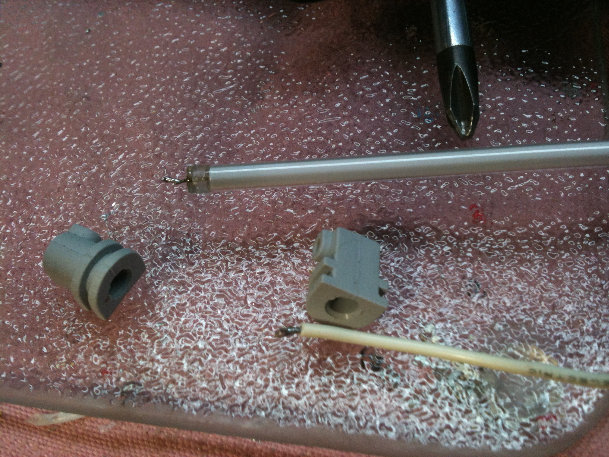
Put the silicon mounts on the ends of the lightbar and place into the display housing slot. Be certain that the SMD resistors are visible. (LEDs are towards the LCD display).
Difficult to see the flexible contact strips for the LCD display in the above photo. The flexible material is translucent.
You can barely make out some dashed patterns along the lower edge of the LCD housing.
In the photo below, take note of the white/black/white strips between the black housing tab and the screw hole for the housing.
Those are the rubber contact strips for the LCD. Same function, but obviously made from a different material.
Ignore the hot glue blobs shown in the photo. It is an outdated photograph. But a good photo showing the two flexible contact strips.

You can fire up the lightbar using an external 12 volt supply now that you have the diodes installed.
Use the same technique as you did with the diodes to make a connection at the other end of the cable. ( It's the connector that will plug into J5501 on the display board)
Insert a component lead (resistor / cap / diode, whatever )into the connector and use them for connection points.
Not a lot to see since the LCD has to be active, but you should barely see something through the LCD.

The photo below shows the housing with the tabs inserted into the circuit board.
Notice how there's a gap under each tab. That's what you're going to reduce by firmly squeezing the housing to the surface of the board. You may wish to wear thin gloves to prevent getting your fingerprints on the surface of the LCD display proper. Much easier to prevent than having to clean them off.

The photo below shows where the tab should be. It's not completely "air-tight" but very close to the circuit board when the housing is seated adequately.

In the photo below notice that the right tab does not appear to be seated down as much as the one on the left.
You're trying to get the housing down as far as possible without causing undue stress on your fingers (and the housing).
If your fingers hurt, you're pressing too hard. Under no circumstances should you use a mechanical aid.
A clamp may not give an indication that the housing is being deformed and can cause the LCD glass to crack.$$$$$

Re-installing the display board.
Now that you've got the housing remounted it's time to re-install the display board.
Check to make sure the MOX and VOX buttons are still in position. Using a long thing screwdriver or similar object.
Hold the button down (towards the front of the panel) with a long thin screwdriver and remove the Q-TIP "handle".
Once both buttons are ready, check for fingerprints on the front of the LCD glass one more time and lower the board into position.
Try to peel back any cables that can be moved out of the way for clearance. You'll be busy juggling the others while slipping the board into place.
You may want to focus on the left side (MOX / VOX button side) first and get the one recessed screw in place.
That first screw pretty well insures that the buttons will not escape during the rest of the process.
The display board should fit into the notches that are on the top of the metal front panel.

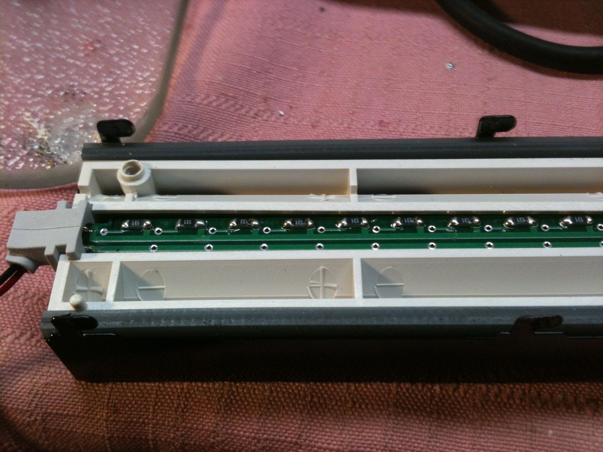
Display variable dimmer modification
The following photo is a closeup with the camera rotated to the left.
Please note the diodes (and one extra if desired) are now mounted on the board.
Also please note the small white connector with a red and black lead. That was originally connected to the CFL inverter supply
from J5501 on the display board.
The pale green/orange/white wire go to the remotely mounted dimmer control pot.
You may mount the dimmer control on the board if desired and "set and forget".

This dimmer module is designed to vary the brightness of the LED array. It is NOT intended to work with the original CFL inverter.
*************************************************************************
Sorry that I didn't consult with Chuck WD8BXS before I drilled my rear panel on the Mark V.
He has an elegant ( and logical ) place for the dimming pot. Inside the little hatch on the top of the rig.
He went the extra mile and mounted it on a tiny sub-board. Thanks Chuck!

One final reminder.....
Take extra care when putting the front top cover back into place(the one with the speaker)
You must be certain that the speaker wires clear the transverse cooling fan impeller.
How do you suppose I know that?.....Hmmm
73 John